Introduction
To install the WF20 Case Former, you will require:
· A spirit level to level the machine.
· Compressed air and electrical power supplies.
-
-
1. Remove the bolts that secure the WF20 to the shipping base.
-
2. Use a forklift to move the machine off its base, with wooden blocks between the forks and the frame.
-
3. While the machine is elevated, install the footpad extensions or castor extensions to the bottom of each leg and adjust them for the desired operating height.
-
4. Position the WF20 where it is to be used.
-
-
-
When selecting the machine location, carefully consider the following points:
-
Adequate access around the machine for correct operation and service.
-
Sufficient room to open the access doors (including control enclosure).
-
A minimum 3-foot clearance in front of the main electrical enclosure.
-
Sufficient clearance for magazine width increases that occur when the machine is set up for large cases.
-
Easy lift-truck access.
-
Good access for magazine loading and nearby space for pallet loads of flat cases
-
Note that the bi-fold doors jut out further when the ‘C’ adjustment is shortened for shorter cases. This increase in machine width should be taken into consideration while ensuring easy access for magazine loading.
-
-
-
1. Set the WF20 for maximum Dimension ‘C’ (with the magazine in the maximum rearward position).
-
2. Use at least a two-foot carpenter level, marked on one end so that you always work to the same bubble line and with the concave side down (if there is one).
-
3. Open the bi-fold door, and position the spirit level along the length of the main frame to level one side of the WF20
-
4. Adjust the machine leveling feet on this side of the machine as appropriate to centralize the bubble between the parallel lines.
-
5. Position the spirit level on the main frame along the width of the machine at the discharge end.
-
6. Adjust the machine leveling feet under the magazine and discharge ends on the opposite side in order to centralize the bubble between the parallels. Tighten the level adjuster lock nuts.
-
7. Position the spirit level on the main frame along the width of machine at the infeed end and repeat step 6.
-
8. Anchor the WF20 to the floor.
-
-
-
If PHSR guarding is installed, the bottom of the guarding should be no more than 6 inches away from the floor.
-
-
-
Service connections (electrical and pneumatic) should ONLY be undertaken by qualified personnel. Observe proper lock-out procedures and recommended sequence to avoid personal injury or damage to the machine.
-
1. Connect the compressed air supply to the inlet end of the manual shutoff valve on the Filter-Regulator unit mounted on the discharge end of the WF20. The air supply should be clean and dry, and the air-line should have a minimum inside diameter of 3/4” (for flexible tubes) or 1” (for steel tubes).
-
2. With the electrical power Off, open the manual shutoff valve and check that the regulator is set to a pressure of 90 PSI.
-
3. After connecting the electrical power, switch the electrical power On; all cylinders should revert to their HOME positions, and there should be no evidence of air leaks.
-
Non-Lube Pneumatic System The WF20 uses a coalescing-type mist separator that effectively removes 99.9% of oil mist from incoming air. Combined with pre-lubricated air cylinders and valves, this system provides reliable pneumatic operation.
-
-
-
Electrical connections should be performed by a qualified electrician.
-
Before attempting any electrical connections check the WF20’s set-up voltage, which is listed on the inside of the access panel of the electrical enclosure (the inside of the door where the touchscreen is located). The Supplementary Manual includes electrical and other details specific to your machine.
-
Where possible, control voltages are 24V DC from a built-in power supply.
-
Electrical power is required to be connected to the designated high voltage terminals on the top of the main electrical disconnect in the top area of the control panel. The machine must also be properly grounded. All wiring must comply with applicable local codes.
-
For a copy of the machine’s wiring diagram, refer to the drawings attached to the manual.
-
-
-
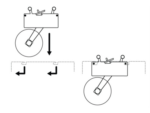
Machines are shipped with the tape head secured in its bracket. To reinstall the tape head, lower them into the brackets to align the pins on their sides with the slots in the bracket.
-
Please consult the tape head manual for instructions on the mounting of tape rolls and the proper threading of tape through the applicator head.
-
-
-
1. Fill the tank with the recommended glue. Ensure that the glue and the tanks are both clean and free of foreign material.
-
2. Turn the Hot Melt unit on. The temperature of the tank, hose and the gun are preset to 330-350º F.
-
3. The temperature gauge indicates the tank temperature. Do not run the machine until the entire system is heated up with the glue completely melted. The melting time usually takes about thirty minutes.
-
Close the hot melt container immediately after filling. An open container will allow entry of paper, lint, dust, etc., into the melted glue. The resulting contamination of the glue will rapidly clog the glue system to the point of requiring complete cleaning of the system and possible replacement of damaged parts.
-
Keep the tank lid closed at all times except when placing new material into the tank.
-

