
Unpublished
This wiki will not appear in search results, but can still be viewed by anyone!
Introduction
The Wexxar limit switch actuator system has become an essential element in our case-forming technology. This system is highly-effective in regulating the flow of cases into the machine, and thus preventing jams and downtime. For that reason, Wexxar has been integrating the limit switch actuators into our case formers since 2008.
As these switches do control case flow, it is important to set them up correctly for the machine to run properly. Different case sizes and different weights of corrugate can imply the need for adjustment to these switch actuators.
Purpose
The purpose of this bulletin is to provide:
- Information for Troubleshooting: tips on how to correctly diagnose problems that may be attributed to the limit switch actuator system, and to eliminate other causes, and
- Instructions: how to adjust the limit switch actuators.
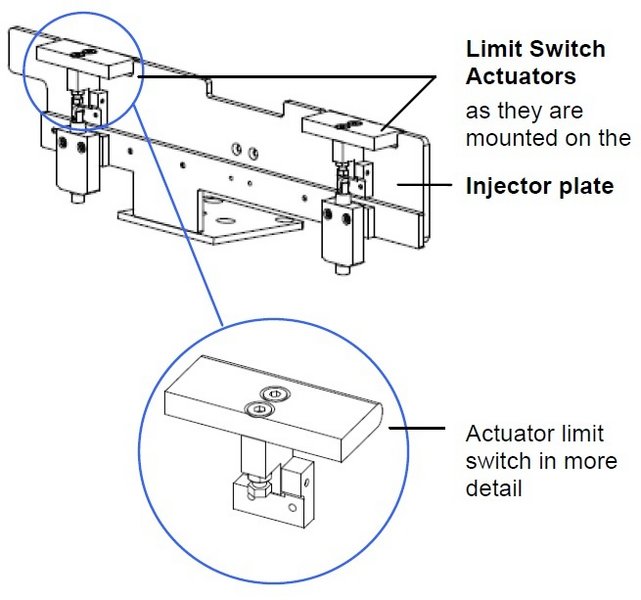
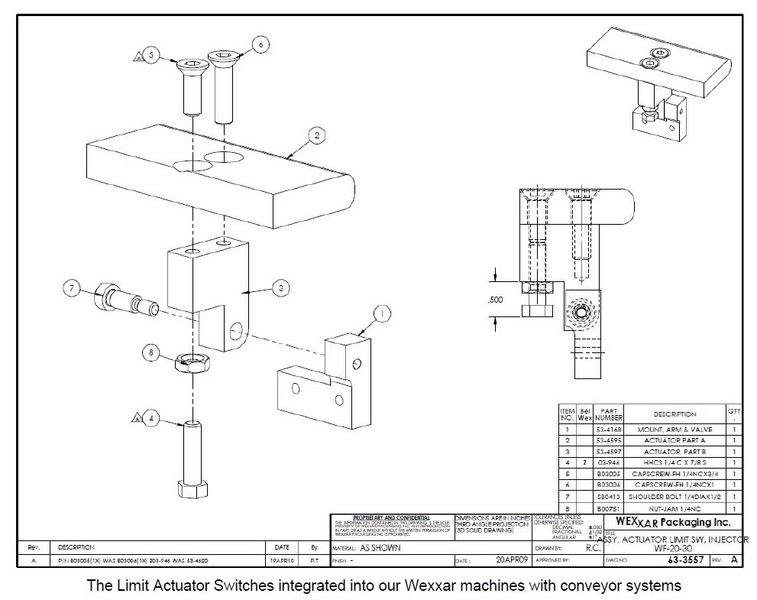
Definition: Limit Switch Actuators
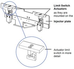
The limit switch actuators are fitted onto the injector plate. As the case blanks are carried along the magazine conveyor belts towards the case-forming section of the machine, they press against the back of the injector plate, effectively pushing against these tabs.
These actuators when pressed, trip the switches. This stops their corresponding conveyors, and signals the case separator and injector into action.
Troubleshooting
WARNING!
ALWAYS LOCK OUT POWER AND AIR SUPPLY before doing any work or troubleshooting on the machine.
Press the E-Stop button or open one of the interlocking guard doors to assure that the air and power are completely shut off and moving parts are disabled.
Problems & Solutions
Eliminating other possible causes.
There are several symptoms when actuators are set incorrectly for the cases being processed. However, these same symptoms may also indicate other issues. Eliminate other possible sources of the problem before deciding to adjust the actuators.
| Problem | Possible Cause | Solution |
|---|---|---|
| Machine has stopped; conveyors have stopped, cases not advancing. | Not enough pressure on an actuator, switch not activated. | Fill the magazine with case blanks. The ‘Empty Magazine’ sensor, not detecting blanks will stop the machine. AND/OR Stack the blanks evenly, eliminating any gaps. |
| The conveyor belt(s) keep(s) running, but the cases are not being separated or loaded into the caliper correctly. | Not enough pressure on an actuator, switch not activated. Check the following: • Is the conveyer belt tension too loose? • Is the distance between the conveyor belts adequate for the case size being processed? In other words, are the conveyor belts aligned as much as possible to the center position of each of the minor case flaps? • Does the magazine pusher arm have enough pressure? • Are the cases are in good condition (not warped)? • Are both belts parallel to the guide rails? • Are any objects physically obstructing the cases from moving forward? (Is an orange quick-adjust handle out of position, blocking cases from advancing?) | If so… Increase belt tension. Re-adjust the spacing between the conveyors. Each belt should be aligned under the center of its corresponding minor flap.* *Note: When this is not possible, due to very large case sizes, align one of the belts to ride under the center of one minor flap, and adjust the width between the belts to the widest possible position. The standard setting is 30 psi. but may vary by weight of cases being processed. Discard warped or damaged cases. Correct the alignment. The outer guide rail should be ¼” wider than the ‘A’ dimension of the box. Clear any obstruction. |
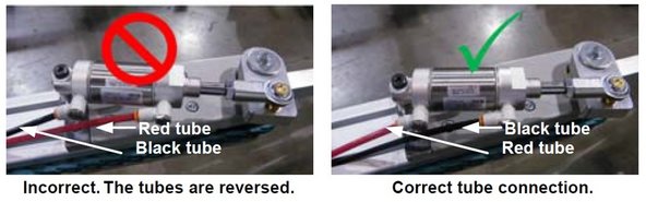
| The blanks jam up into the injector and separator area preventing these from working properly. | Too much pressure on an actuator. Check the following: • Is there too much pressure from the pusher arm? • Has anyone used physical force to push or kick the blanks forward? • Are the pneumatic tubes connected to the magazine belt-feed cylinder correctly? | Reduce the amount of pressure being applied.* *Note: Pressure should be at or around 30 psi; slightly less for light-weight blanks and slightly more for heavier ones. Avoid using any additional physical force on the stack of blanks. Make sure the pneumatic tubes are connected as shown in the images below with the black tube connected to the rod-end of the cylinder. |
 | ||
Guideline: Adjusting the Limit Switch Actuators
Once these other possible causes have been discarded, review the following sections to adjust the limit switch actuators.
Initial Setup Position
At the standard factory set-up, the switches are activated when the tabs are pushed back to the position shown.
At this calibration, the edge of the tab goes no further than the center of the thickness of the injector plate, when pulled back (towards the out-feed end of the machine).
| IMPORTANT: Adjust to apply the minimum amount of force necessary to trip the switches. This practice will extend the life of both the machine’s separator and injector functions. |
|---|
Accessing the Limit Switch Actuators
To gain access to the actuators for calibration:
- Press the E-Stop button & lock out air & power to the pneumatic system.
- Open the bi-folding door and push the discharge pusher toward the out-feed end of the machine to gain unobstructed access to the limit switch actuators, (shown below).
Calibration Steps
1. Analysis: Are the tabs too sensitive or not sensitive enough (in relation to contact with the oncoming blanks)?
| Problem | Applicable Description | Corrective Action |
|---|---|---|
| Blanks are stacking too loosely | Actuators are too sensitive—they activate the switch too soon. | Make the switch less sensitive: tighten the bolt. |
| Blanks are stacking too tightly and are jamming | Actuators are not sensitive enough—they don’t activate the switch, or not soon enough. | Make the switch more sensitive: loosen the bolt. |
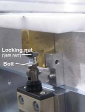
2. Using 7/16” wrenches, loosen the locking nut or ‘jam nut’ on the switch, just below the white plastic tab and brass actuator block.
3. In increments of ¼ turn: loosen or tighten the switch bolt or depending on your analysis above.
4. Troubleshoot: After each ¼ turn adjustment, jog the machine through the cycle to check for adequate functioning.
Illustration
0 Comments